Showing posts with label Technical. Show all posts
Wednesday, October 11, 2023
Space Frame Structure
How to model a curtain panel roof on the space frame structure like above?
First of all, based on the "Metric Curtain Panel Pattern Based.rft", create an adaptive family under Curtain Panels family category.
Then, create a Model In-Place family under the Mass family category for the required roof shape.
Choose the required surface of the Mass and apply the Pattern as the divided surface before you replaced with the loaded Adaptive Curtain Panel family.
The rigid frame of the roof can be modelled with the Model In-Place with sweep.
The rigid panel can be modelled with the Structural Beam Systems and perimeter framing and support framing can be modelled with the Structural Trusses. The mast modelling may need void form mass.
After adjusting the size and visibility control of the panel and members instance parameters of each adaptive curtain panel family the completed Curtain Panel roof with space frame structure are shown below.
Cheers!
Friday, August 20, 2021
Internal Origin and Unclipped Project Base Point
Start from Revit 2020.2, the clip of the Project Base Point
is not available and the Project Base Point is unclipped with the Startup
Location which is now visible and called Internal Origin.
By Default, the Internal Origin, the Project Base Point and the Survey Point are placed in the same location.
If we look Singapore survey system, it is not possible to type in the coordinates directly into unclipped Project Base Point. Since the Project Base Point cannot place more than 10 miles (16 kilometers) from it's Startup location, while moving the Project Base Point, you would receive the following error:-
Moving the Project Base Point together with Internal Origin is important as we are moving the model around the site while the Survey Point is acting as a real-world relation to the Revit model.
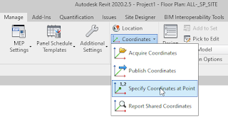
If you want to set the Project Base Point to the known Boundary Station Point given by your surveyor in 2020.2.2 and later versions, go to Manage > Coordinates > Specify Coordinates at Point.

Select the Project Base Point in order to move it to the selected Boundary Station Point. From the Specify Shared Coordinates dialog, fill in the Northing and Easting values of selected Boundary Station Point given by the Surveyor.
Labels:
BIM,
Technical,
Tips and Tricks
Saturday, June 16, 2012
BCA’s Code Checking within Revit
Architects in
Singapore are required by law to design in compliance with Code on
Accessibility in the Built Environment 2007 (Barrier-Free Accessibility Code).
By creating special Revit families, we can check some of these requirements that
all architects are familiar with. In this example, we can modify a Revit door
family to enable Minimum Doorway Manoeuvring Space checking between the door
and other model elements such as walls. The evaluation can be determined by
hovering over a door to see clearances or by using Revit’s Interference Check
tool. This door type specifically tests minimum front approach clearances for a
door as defined by Accessibility Code 2007 clause 3.8.4, as shown in Figure 1. These represent very common
door clearance conditions.
Figure 1 – Minimum Doorway Manoeuvring Space (Accessibility Code
2007)
Our custom door
will allow Minimum Doorway Manoeuvring Space checking to be used in two ways:
(1) By hovering over a door, or (2) By using the Interference Check tool.
When we hover over
the door type, outline linework displays to indicate the Minimum Door
Manoeuvring Space clearance area. Similar display occurs when the door is
selected.
Our custom door
contains extrusions that represent the 3D volume of the Minimum Door
Manoeuvring Space clearance. Type Parameters and Formulas are used to control
the extrusion location between different door sizes and wall types. These
extrusions are hidden in the project views but allowed the user to turn on or
off in views via a visibility parameter. The families also have the 2D graphics
as an object style to allow the user to turn on or off on floor plan views.
Figure 2 – Hovering over door displays Minimum Door Manoeuvring
Space clearance boundaries
Figure 3 – Extrusions in door family
Even though the
extrusions are hidden in the model, Interference Check detects collisions
between them and other objects.
Figure 4 – Highlighted wall interferes with Minimum Door
Manoeuvring Space clearance
Figure 5 – Visibility of 3D extrusion and 2D boundary lines can be
control by Type parameter
Checking Minimum
Door Manoeuvring Space clearance is an architectural task that happens on most
building types other than single family residential. Using customized door
families will make this process easier and ultimately reduces errors in our
design.
(Reference: Autodesk WikiHelp. ADA Door
Clearance Checking using Revit Interference Tool)
Labels:
Technical
Saturday, July 23, 2011
Startup Location, Project Base Point and Survey Point
Every project has a startup location (true origin), project base point and a survey point, although they might not be visible in all views, because of visibility settings and view clippings. They cannot be deleted.
The startup location is the internal project origin and fixed on the plate having 1 mile (10 miles for 2011) radius. It is equivalent to the WCS Origin in a CAD (.dwg). Based on that origin and coordinate system, you can then have multiple locations in the form of shared coordinate systems with their own origin and orientations. So if you want to move your linked files around, you have to link them by Shared Coordinates and not by Origin to Origin as that will always land them at the same spot.
The project base point defines the origin (0,0,0) of the project coordinate system. It also can be used to position the building on the site and for locating the design elements of a building during construction. Spot coordinates and spot elevations that reference the project coordinate system are displayed relative to this point.
The survey point represents a known point in the physical world, such as a geodetic survey marker. The survey point is used to correctly orient the building geometry in another coordinate system, such as the coordinate system used in a civil engineering application.
Consider the following when working with project base points and survey points:
The startup location is the internal project origin and fixed on the plate having 1 mile (10 miles for 2011) radius. It is equivalent to the WCS Origin in a CAD (.dwg). Based on that origin and coordinate system, you can then have multiple locations in the form of shared coordinate systems with their own origin and orientations. So if you want to move your linked files around, you have to link them by Shared Coordinates and not by Origin to Origin as that will always land them at the same spot.
The project base point defines the origin (0,0,0) of the project coordinate system. It also can be used to position the building on the site and for locating the design elements of a building during construction. Spot coordinates and spot elevations that reference the project coordinate system are displayed relative to this point.
The survey point represents a known point in the physical world, such as a geodetic survey marker. The survey point is used to correctly orient the building geometry in another coordinate system, such as the coordinate system used in a civil engineering application.
Consider the following when working with project base points and survey points:
- To ensure accuracy of the model, be sure the model geometry is less than 1 mile (10 miles for 2011) from the startup location of the project base point. To check this measurement:
- Use Move to Startup Location from the shortcut menu to move the project base point back to its startup location.
- Use the Measure tool on the Modify tab to measure the distance from the project base point to the model geometry.
- If the distance is more than 1 mile (10 miles for 2011), move the model geometry within 1 mile (10 miles for 2011) of the startup location of the project base point.
- Before you export a building site to a civil engineering application that accepts ADSK files, such as Civil 3D:
- Move the unclipped survey point to the location agreed upon with the civil engineer.
- Use the Specify Coordinates at a Point tool or enter the coordinates on the Site tab of the Building Site Export dialog, using the coordinates provided by the civil engineer.
- To ensure that an imported DWG site is positioned correctly in the project:
- Using the coordinates you received from the civil engineer, specify the shared coordinates of the survey point.
- Specify the correct angle for True North. Specify Positioning-Auto by Shared Coordinates to link the DWG file.
Labels:
Technical
Monday, June 6, 2011
Central file & Local file in Revit
In many projects, most of the time the schedule get tight and the project management wants to add more team members to meet a deadline. In 2D CAD environment, we need to split the files and give them to new team members to help meet a deadline.
In a Revit project, we can have a single model file called central file which is the main file that holds all of the worksets. This central file is created by the BIM Manager or Project Leader and stored on a server, enabling multiple users to access it and work on the same model simultaneously. After creating a central file with user-created worksets, you need to copy it and saved it in your local computer as a local file. When you are helping the project, this local file is to modify and save locally and synchronize it with the central file.
Workset is a collection of related elements in a project in which an individual team member would work on. Worksets are part of the worksharing process, allow you to divide up portions of the model. In 2D CAD environment, we can have separate layers and named views and can use the partial open option to select which view and layer geometry (graphical objects only) that you want to work with in a drawing. In Revit, worksets are similar to those layers and named views but more like the building assemblies and components and each workset can be selected to load or not to load when you open a project.
Labels:
Technical
Subscribe to:
Posts (Atom)